Distributed Generation Definition:
Power generation systems that distribute power are called distributed power generation systems (DPGSs). Several types of power plants are used worldwide to generate electrical power. They do not require a centralized electricity grid to transmit power over long distances.
However, they are located at the point of use, so energy is used close to where it is produced. They can be used in various applications, such as generating clean, renewable energy, providing backup power, and reducing carbon dioxide emissions.
Background: What is Distributed Generation?
For nearly two decades, utility companies have continuously struggled to capture what is referred to as “distributed generation” as an alternative to generating electric power for their consumers. Distributed generator means smaller and additional local sources of electric power, such as distributed generation solar and wind turbines.
Furthermore, types of distributed generation are photovoltaic panels, fuel cells, wind turbines, etc. Energy generation, if there is enough of it, would be closer to the people who need the energy and not just close in terms of distance but also actually see the people making the decisions about power production and distribution. Rather than utility companies making those decisions, someone like you would.
Introduction: Distributed Generation Solar, Wind:
We must reduce the use of fossil fuels and switch to renewable sources such as wind, solar, and geothermal energy. Many renewable energy technologies include solar photovoltaic, wind turbines, biogas, and bio thermal systems, which use sunlight, wind energy, etc. These renewable energy sources generate electricity and transform it into an appropriate form of energy.
Wind turbines are a common form of renewable energy technology that is used to harness wind power and convert it to electricity for use in homes and industries. With many electric car owners, it is easy to conclude that electric cars have become increasingly popular.
Take a look at the article, Solar and Wind Distributed Generation
Description: Benefits of Distributed Generation:
Distributed applications pose exceptional benefits, produce electricity for on-site injection, and intersect with low-voltage transformers. Incorporation of DG can shrink transmission line losses, improves grid resilience, avoid extra generation expenses, and decrease the necessity to spend on new utility generation capacity. Through proper calibration, electric utility systems aiming for energy development by distributed PV allocation have multiple benefits and provide backup in case of disturbance.
What is the MATLAB code?
MATLAB is designed for engineers and scientists to express mathematical matrices and data arrays directly. It is possible to use MATLAB to do any programming, from simple interfaces to extensive application development.
Proposed Methodology: Power System Analysis MATLAB
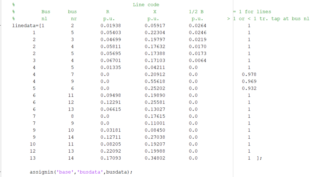
The scheme compromises a MATLAB simulation through the genetic algorithm in a power system for the optimal location and sizing of distributed generation in a distribution grid. The objective function comprises both power losses (real and reactive) and voltage profiles, and the techniques are verified on the IEEE 14 bus system data.
Visit the link for further learning Matlab script, Load Flow Analysis using Matlab Code. Learn more about the keys to content writing.
Basic Load Flow MATLAB Code Free Download
Distributed Generation MATLAB Code free download with the following link
%Topic
% -----------------------------
% Implementation of Distribution Generator (IDG) Algorithm for Performance
% enhancement of Distribution Feeder under extreme load Growth
% -----------------------------

%%
clc
close all;
% Login
disp('Would you like to change values')
Start_Program=input('Use stored values press=0, To store new values press=1\n Enter Value:');
if Start_Program==0;
%--------------------------------------------------------------------------
load DG_Variable


% ORignial R Z Table
Res_Array=[0.30408 0.07896 0.52848 0.204624 0.061488 0.032928 0.27888 0.076944 0.2924 0.099104 0.356576 0.140112 0.030576 0.095088 0.335936 0.016464 0.190848 0.283248 0.129024 0.177408 0.146496 0.528528 0.445952 0.405968 0.030576 0.397152 0.371904 0.135072 0.503568 0.30752 0.498432 0.090576 0.10752 0.163968 0.993392 0.015952 0.278208 0.091904 0.134064 0.061488];

imp_Array=[0.0607 0.1189 0.2607 0.308 0.0926 0.0496 0.4198 0.1158 0.3391 0.5094 0.5357 0.2109 0.046 0.1431 2.0511 0.5248 0.1128 0.001 0.2942 0.267 0.2205 0.5955 0.9702 0.31 0.046 0.5978 0.1082 0.1033 0.2455 0.1618 0.284 0.046 2.1618 0.1468 0.2642 0.2702 0.4188 0.4404 0.2018 0.2926];


elseif Start_Program==1;
N=input('Number of Nodes=');
Total_Load=input('Total Load During Survey=');
Ref_Voltage=input('Voltage at Refrence node=');
Limits_Calculation=(Ref_Voltage*5)/100;
Lower_Limit=Ref_Voltage-Limits_Calculation;
Upper_Limit=Ref_Voltage+Limits_Calculation;
% Variable Initialize
%----------
Seg_Current=zeros(1,N);
Seg_V_Drop=zeros(1,N);
Node_Voltage=zeros(1,N);
Node_Current=zeros(1,N);
%------
Imp_Array=zeros(1,N);
Load_Array=zeros(1,N);
Res_Array=zeros(1,N);
%------
Power_Loss=zeros(1,N);
%DG_Checker=zeros(1,N);
h=zeros(1,N);
Sr=(1:N)';
%% Inputs Loops
for ii=1:N;
fprintf('Node----%d\n',ii) % Node VOltages loop
Load_Array(ii)=input('Enter node Load=');
fprintf('Impedance=%d\n',ii)
Imp_Array(ii)=input('Put Impedence Value:');
fprintf('Resistance=%d\n',ii)
Res_Array(ii)=input('Put Resistance Value:');
end
%-----------
% Node Array0
for ii=1:N;
Node_Current(ii)=Load_Array(ii)/(sqrt(3)*Ref_Voltage);
end

save DG_Variable1

% Start program if/else.
else
disp('Error:, Run Program Again:')
end
%% Calculation Without DG
%--------------------------------------------------------------------------
Seg_Current(1)=(Total_Load)/(sqrt(3)*Ref_Voltage);                         %Total Current Supplied By the Source at Reference Node
Seg_V_Drop(1)=Imp_Array(1)*Seg_Current(1);                                 % Voltage Drop of Segment Between Node 0 and 1
Node_Voltage(1)=Ref_Voltage-Seg_V_Drop(1);                                 % Voltage at Node 1
Power_Loss(1)=(Seg_Current(1)^2)*Res_Array(1);
%------------------
for ii=2:N
Seg_Current(ii)=Seg_Current(ii-1)-Node_Current(ii-1);                        %Calculating and Storing Segment Current
Seg_V_Drop(ii)=Imp_Array(ii)*Seg_Current(ii);                            %Calculating Voltage Drop of the Segment under Consideration
Node_Voltage(ii)=Node_Voltage(ii-1)-Seg_V_Drop(ii);                        % Calculating and Storing Node Voltages in Array
Power_Loss(ii)=(Seg_Current(ii)^2)*Res_Array(ii);
end
%% Results
% format long g
Total_Voltage_Drop_Without_DG=sum(Seg_V_Drop);
Total_Power_Loss_Without_DG=sum(Power_Loss);
sprintf('Total_Voltage_Drop_Without_DG=%d, Total_Power_Loss_Without_DG=%d'...
,Total_Voltage_Drop_Without_DG,Total_Power_Loss_Without_DG)
% format short

%% Ploting
z= Node_Voltage/11000;
y=Power_Loss/1000;
    %% DG CHECKER
   for n=1:N
 if Node_Voltage(n)>=Lower_Limit && Node_Voltage(n)<=Upper_Limit
    h(n)=1;
elseif Node_Voltage(n)>Upper_Limit
    h(n)=2;
else
    h(n)=0;
 end
    end
%% EXCEL Without DG
DG_Checker=h';                 % Checker=h'; %('0-DG Require,1-No DG Require, 2-Greater than Limits')
SegCurrent=Seg_Current'; %Segment_current
VolDrop=Seg_V_Drop'; %Seg_Voltage_Drop
NodeVoltage=Node_Voltage';         %Node_Voltage
PowerLoss=Power_Loss';
%EXCEL
T =table(Sr,SegCurrent,VolDrop,NodeVoltage,PowerLoss,DG_Checker);          % Sr intialize in start
T(:,1:6);
excel_file = 'DG_Algo.xlsx';
writetable(T,excel_file,'Sheet',1,'Range','B1');


%% DG Implementation
%--------------------------------------------------------------------------
%----------

h=zeros(1,N);
Sr=(1:N)';
%------
Power_Loss_Cmp=0;
%------
for i=100:308.2     %Default 308.2                                                               %DG1 SIZE
DG1_Current=i;
for j=7:20     %Default 17                                                                 % DG2 POSITION
       for k=100:276    %Default 276.5                                                     %DG2 SIZE
DG2_Current=k;
           for l=22:40 %Default 30                                             % DG2 POSITION
Total_Dg_Current= DG1_Current+DG2_Current;
for o=1
%-------------- Just for Manual Checking
Power_Loss=zeros(1,N);
Seg_Current=zeros(1,N);
%--------------
Seg_Current(1)=(Total_Load)/(sqrt(3)*Ref_Voltage);
Seg_Current(1)=Seg_Current(1)-Total_Dg_Current; % all 1 not I.
end
for m=2:j-1
Seg_Current(m)=Seg_Current(m-1)-Node_Current(m-1);
end
for g=j                                                    %DG1-Position
Seg_Current(g)=Seg_Current(g-1)-Node_Current(g-1);
Seg_Current(g)=DG1_Current+Seg_Current(g);                  %---- DG1-Addition
end
n=j+1;
for v=n:l-1;             % g + one: L-one
Seg_Current(v)=Seg_Current(v-1)-Node_Current(v-1);         % Calculating and Storing Segment Current
end                                                     %DG2-Position
for g=l
Seg_Current(g)=Seg_Current(g-1)-Node_Current(g-1);
Seg_Current(g)=DG2_Current+Seg_Current(g);                  %---- DG2-Addition
end
m=l+1;                 %L + one.
for u=m:N;             % g + one: L-one
Seg_Current(u)=Seg_Current(u-1)-Node_Current(u-1);        % Calculating and Storing Segment Current
end
                 %%

%--------------------------------------
Seg_V_Drop(1)=Imp_Array(1)*Seg_Current(1);                                 % Voltage Drop of Segment Between Node 0 and 1
Node_Voltage(1)=Ref_Voltage-Seg_V_Drop(1);                                 % Voltage at Node 1
for ii=2:N
Seg_V_Drop(ii)=Imp_Array(ii)*Seg_Current(ii);                            %Calculating Voltage Drop of the Segment under Consideration
Node_Voltage(ii)=Node_Voltage(ii-1)-Seg_V_Drop(ii);                        % Calculating and Storing Node Voltages in Array
end


   for n=1:N
 if Node_Voltage(n)>=Lower_Limit && Node_Voltage(n)<=Upper_Limit
    h(n)=1;
elseif Node_Voltage(n)>Upper_Limit
    h(n)=2;
else
    h(n)=0;
 end
   end
    %-------


%-------------
 if h(1:N)==1

                    for g=1:N
               Power_Loss(g)=(Seg_Current(g)^2)*Res_Array(g);
                    end
Power_Loss_Sum=sum(Power_Loss);
%-------------
               if Power_Loss_Cmp==0                                        %Power_Loss_Cmp=0, In the Start,
               Power_Loss_Cmp=Power_Loss_Sum;
               DG1_Location=j;DG1_Current_Size=i;DG2_Location=l;DG2_Current_Size=k;
               else
               end


               if Power_Loss_Sum<Power_Loss_Cmp   %Power_Loss_Cmp=0, In the Start,
                   Power_Loss_Cmp=Power_Loss_Sum;


                   DG1_Location=j;DG1_Current_Size=i;DG2_Location=l;DG2_Current_Size=k;

               else
               end

 else
 end


           end
       end
end
end

sprintf('DG1-Position=%d, DG1-Current=%d, DG2-Position=%d, DG2-Current=%d'...
    ,DG1_Location,DG1_Current_Size,DG2_Location,DG2_Current_Size)
                   j=DG1_Location;i=DG1_Current_Size;l=DG2_Location;k=DG2_Current_Size;
                   Total_DG_Current=DG1_Current_Size+DG2_Current_Size;
                   Seg_Current_Without_DG=(Total_Load)/(sqrt(3)*Ref_Voltage);
                   Total_Source_Current_With_DG=Seg_Current_Without_DG-Total_DG_Current;
sprintf('Total_Source_Current_With_DG=%d',Total_Source_Current_With_DG)
%%
Seg_Current=zeros(1,N);
Seg_V_Drop=zeros(1,N);
Node_Voltage=zeros(1,N);
Power_Loss=zeros(1,N);
%DG1_Location=j,DG1_Current_Size=i,DG2_Location=l,DG2_Current_Size=k,
Seg_Current(1)=Total_Source_Current_With_DG;
Seg_V_Drop(1)=Imp_Array(1)*Seg_Current(1);
Node_Voltage(1)=Ref_Voltage-Seg_V_Drop(1);
Power_Loss(1)=(Seg_Current(1)^2)*Res_Array(1);
for m=2:j-1
Seg_Current(m)=Seg_Current(m-1)-Node_Current(m-1);
Seg_V_Drop(m)=Imp_Array(m)*Seg_Current(m);
Seg_V_Drop(m)=abs(Seg_V_Drop(m));
Node_Voltage(m)=Node_Voltage(m-1)-Seg_V_Drop(m);
Power_Loss(m)=(Seg_Current(m)^2)*Res_Array(m);
end
%------------------
for g=j            %DG1_Location=j
Seg_Current(g)=Seg_Current(g-1)-Node_Current(g-1);
%----
Seg_Current(g)=DG1_Current_Size+Seg_Current(g);       %DG_1 ADDED
%---
Seg_V_Drop(g)=Imp_Array(g)*Seg_Current(g);                                 %Voltage Drop of Segment Between Node 0 and 1
Seg_V_Drop(g)=abs(Seg_V_Drop(g));
% Node_Voltage(g-1)=11000-Seg_V_Drop(m);
Node_Voltage(g)=11000-Seg_V_Drop(g);                                 %Voltage at Node 1

Power_Loss(g)=(Seg_Current(g)^2)*Res_Array(g);
end
%-------------------
n=j+1;
for u=n:l-1;          %DG2_Location=l           % g + one: L-one
Seg_Current(u)=Seg_Current(u-1)-Node_Current(u-1);                         %Calculating and Storing Segment Current
Seg_V_Drop(u)=Imp_Array(u)*Seg_Current(u);                                 %Calculating Voltage Drop of the Segment under Consideration
Seg_V_Drop(u)=abs(Seg_V_Drop(u));
Node_Voltage(u)=Node_Voltage(u-1)-Seg_V_Drop(u);                           %Calculating and Storing Node Voltages in Array
Power_Loss(u)=(Seg_Current(u)^2)*Res_Array(u);
end
%-------------------
for g=l             %DG2_Location=l
Seg_Current(g)=Seg_Current(g-1)-Node_Current(g-1);
%------
Seg_Current(g)=DG2_Current_Size+Seg_Current(g);          %DG_2 ADDED
%------
Seg_V_Drop(g)=Imp_Array(g)*Seg_Current(g);                             % Voltage Drop of Segment Between Node 0 and 1
Seg_V_Drop(g)=abs(Seg_V_Drop(g));
% Node_Voltage(g-1)=11000-Seg_V_Drop(u);
Node_Voltage(g)=11000-Seg_V_Drop(g);                                     % Voltage at Node 1
Power_Loss(g)=(Seg_Current(g)^2)*Res_Array(g);
 end
%-------------------
n=l+1;     %L + one.
for u=n:N;             % g + one: L-one
Seg_Current(u)=Seg_Current(u-1)-Node_Current(u-1);        % Calculating and Storing Segment Current
Seg_V_Drop(u)=Imp_Array(u)*Seg_Current(u);                % Calculating Voltage Drop of the Segment under Consideration
Seg_V_Drop(u)=abs(Seg_V_Drop(u));
Node_Voltage(u)=Node_Voltage(u-1)-Seg_V_Drop(u);                        % Calculating and Storing Node Voltages in Array
Power_Loss(u)=(Seg_Current(u)^2)*Res_Array(u);
end

%% Results
format long
Total_Voltage_Drop_With_DG=sum(Seg_V_Drop);
Total_Power_Loss_With_DG=sum(Power_Loss);
sprintf('Total_Voltage_Drop_With_DG=%d, Total_Power_Loss_With_DG=%d'...
    ,Total_Voltage_Drop_With_DG,Total_Power_Loss_With_DG)
format short
% %% Ploting
% % Node Voltage
% z1=Node_Voltage/11000;
% x=1:N;
% % subplot(2,1,1)
% figure
%
%  plot(x,z,'k:',x,z1,'r','linewidth',1.3)
%
% % bar(x,z)
% legend('W/O DG','W DG',3)
% axis([1 40 0 1.05])
% xlabel('Node Numbers')
% ylabel('Per Unit')
% title('Voltage Profile')
% % Power Loss
% y1=Power_Loss/1000;
% % subplot(2,1,2)
% figure
% plot(x,y,'k:',x,y1,'r','linewidth',1.3)
% % bar(x,y)
% legend('W/O DG','W DG',1)
% axis([1 40 -5 170])
% xlabel('Node Numbers')
% ylabel('Power Loss(Kw)')
% title('Power Loss')
%% DG CHECKER
    for i=1:N
 if Node_Voltage(i)>=Lower_Limit && Node_Voltage(i)<=Upper_Limit
    h(i)=1;
elseif Node_Voltage(i)>Upper_Limit
    h(i)=2;
else
    h(i)=0;
 end
    end
%     format longEng
%% EXCEL FOR DG
DG_Checker=h';                 % Checker=h'; %('0-DG Require,1-No DG Require, 2-Greater than Limits')
SegCurrent=Seg_Current'; %Segment_current
VolDrop=Seg_V_Drop'; %Seg_Voltage_Drop
NodeVoltage=Node_Voltage';         %Node_Voltage
PowerLoss=Power_Loss';
% %EXCEL
T =table(Sr,SegCurrent,VolDrop,NodeVoltage,PowerLoss,DG_Checker);          % Sr intialize in start
T(:,1:6);
excel_file = 'DG_Algo.xlsx';
writetable(T,excel_file,'Sheet',1,'Range','J1');


The planned scheme encloses a set of procedures that regulate each bus’s DG placement suitability index in the distribution network. The optimum allocation of the DG unit is achieved using mathematical formulation. The study comprises an assessment between the planned approaches and displays the significance of installing the perfect proportion of DG in the most suitable place.
Click the link for the particle swarm optimization example code for the 33 bus radial distribution system.
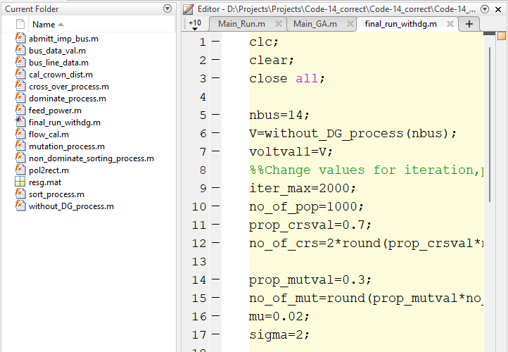
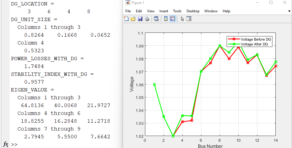
Simulation executed as mentioned below and genetic algorithm in power system provides efficient performance.
· Without DG
· Optimal Location and Sizing of DG Using Genetic Algorithm (1, 2, 3, 4) DGs combination – 14 Bus System IEEE – Genetic Algorithm
· 14 IEEE Bus System with 1, 2, 3, 4 DGs (Optimal Location and Sizing) using Genetic Algorithm
Without DG Results

A Deep Dive into Distributed Generation MATLAB Code
This article can help you understand the fundamentals of practicing MATLAB code for power flow analysis and renewable power systems. It is a tutorial to clarify how power system analysis is performed in order to help you understand MATLAB for renewable power systems and smart grid systems. The subjects discussed will include network modeling, optimal placement meaning, and newton Raphson method MATLAB code.

Why Newton-Raphson method is better?
Newton Raphson method is considered the most sophisticated numerical approach to solving non-linear equations and power flow analysis.
Gauss-Seidel is a simple iterative method where partial derivatives are not required to solve n number of equations. Newton Raphson’s method relies on Taylor’s series and partial derivatives.
The recent Newton Raphson method MATLAB code examples require less number of iterations to reach convergence and take less computer time; hence, the computation cost is less, and convergence is inevitable. The N R method is more precise and is not responsive to elements like regulating transformers, slack bus selection, etc.

The drawbacks of this method are the difficult solution technique, more calculations involved in each iteration resulting in large computer time per iteration, and the large requirement of computer memory, but the drawback has been overwhelmed through a compact storage scheme.
Newton Raphson load flow analysis using MATLAB code is performed as presented below.

Newton Raphson Method MATLAB Code Example
What is the purpose of the load flow study?
Load flow analysis is used most commonly to evaluate the system’s operation, while dynamic analysis is used for detecting unavailable elements during a period. It checks whether a system operates safely and if the equipment has been overloaded.
What is a Genetic Algorithm and its advantages?
A Genetic Algorithm is a method used to generate solutions to some complex issues based on the survival of the fittest theory of Charles Darwin. In short, all of us will have heard of Darwin’s famous theory of Evolution by Natural Selection. We will learn about how it applies to genetic algorithms.
This algorithm reflects the process of natural selection. The fittest individuals are selected for reproduction, and this results in the production of offspring of the next generation. Evolutionary algorithms are a type of Genetic Algorithm typically used to generate high-quality solutions to optimization and search problems.
Genetic Algorithm Load Flow is considered during the evaluation of this article.
Looking for particle swarm optimization code, click on the below link
Voltage Profile Improvement & Power Loss Reduction
A power distribution system (PDS) is a complex system comprising numerous interconnected loads and power sources, which must be carefully managed to avoid a cascading effect of load losses and voltage profile deterioration. This work proposes an optimal method for optimizing NR problems in a PDS for power loss reduction and VP improvement.
The current study presents the use of an algorithm based on GA for optimizing the network parameters in the NR process to reduce the power loss of the IEEE 14 mesh distribution system and improve the VP performance of the network. This model has been developed using MATLAB R2017a software.

Why is voltage profile important?
As voltage profile decreases in the network, re-powering demands increase. Unless reactive power demand is met, bus voltage decrease can cause further cascading of neighboring regions. Therefore, maintaining voltage within the allowed limit is essential.
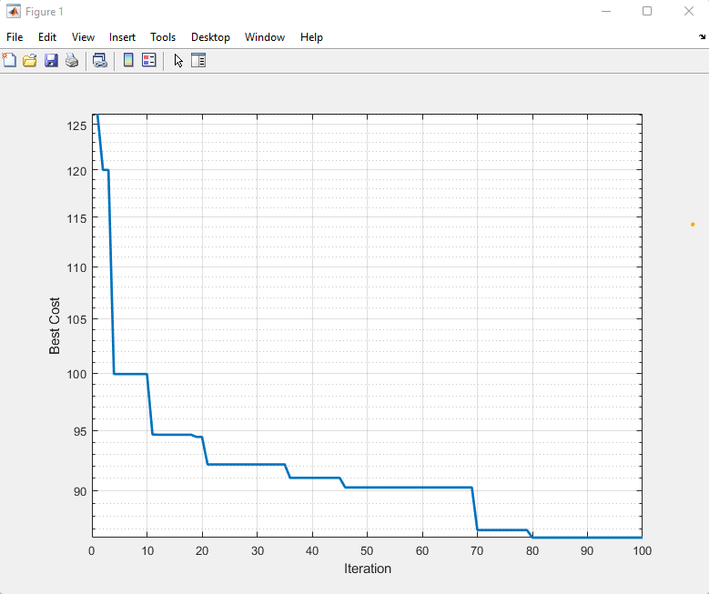
Using Convergence graph in MATLAB to Review Results
A convergence plot can decide whether a performed analysis is converged acceptably. In a graph representing good convergence of a measured quantity, the curve based on results becomes asymptotic as it processes iterations. Here in the attached plot, as load flow analysis using MATLAB code progress along with iteration, the results satisfied the performance of a considered approach.

Conclusion:
Optimal location and sizing of distributed generation MATLAB code are proficient in enhancing the voltage profile of the network and shrinking power loss, eventually reducing the network congestion as well.
Interested in further learning, here is a playlist of complete simulation tutorials related to this topic.
As a simulation tutor team, we cooperate with university scholars and entrepreneurs and participate in industrial projects to share knowledge related to simulation and engineering problems. We connect different members worldwide to execute the optimized solution and assist them in how to benefit from published articles and obtain optimized solutions per their requirements.
Click on the below link and continue learning
Load Flow Analysis via Matlab Script & Simulink Model
Looking for similar implementation, mathematics support, or MATLAB Programming subscribe to the newsletter.
The End.

I need this code
Dear sir, Can you please send me the matlab code, sharing my email nattanapong@live.com
Thanks in advance
Check your email.
Sir, Please share matlab code with me at uetianshafiq@gmail.com
Dear sir, Can you please send me the matlab code
Check your email.
Dear sir,
Your video is very useful for me. I m lecturer in engineering college.
If u pls send matlab code for 38 thoughts on “Optimal Location and Sizing of Distributed Generation” to students in laboratory.
Kindly do the needful
Thank you in advance
kesavan.t@eec.srmrmp.edu.in
Sir can you please share the code to me.
This is my mail address kiranadigopula9491@gmail.com
not received sir
Can you please send me the matlab code once again
Check your email, or contact me by email. contact@simulationtutor.com
Sir pls send me the code on mail id rupikagandotra01@gmail.com
vishnu can you send me the code at 2002bhaskar8@gmail.com
Can you please send me the matlab code, thanks.
Check your email.
Dear sir, Can you please send me the matlab code, sharing my email moshoodakanni4u@yahoo.com
Thanks in advance
Check your email.
Dear Sir/Madam,
Can you please send me this MATLAB code to mail id: avvari.ravi@gmail.com.
It is for educational purposes only.
Respond sent.
Dear sir , can you please send me the matlab code for PSO for IEEE69 . My email is chenghowcow@gmail.com. Thanks in advance !!
Check your email, and let’s discuss further.
Dear sir, Can you please send me the matlab code of otimize placemebt of Ev charger on ieee 33 bus system
sharing my email
adilamin606@gmail.com
Thanks in advance
Check your email, and let’s discuss further.
Dear sir, Can you please send me the matlab code, sharing my email ankitgrg4289@gmail.com
Check your email and let’s discuss further
Pingback: Getting Started with Matlab - simulationtutor.com
Check your email, and let’s discuss further.
Sir, can you please share this matlab code ? On this given email address.
ggate1998@gmail.com
Check your email.
Dear sir, Can you please send me the matlab code, sharing my email kienb1703172@student.ctu.edu.vn
Thanks in advance
Respond sent.
Dear sir, Can you please send me the matlab code, my email hauser.z0329@gmail.com.
Dear sir/madam, can you please send me the matlab code
Sent.
Could you please share this code with me? Thanks in advance
Sent.
Please can you send me code for IEEE 33
Can you send me the code in my mail
Sent.
Can you send me the code in my mail
Reply Sent.
Can you please send me the matlab code, thanks.
Dear sir, Can you please send me the matlab code, sharing my email hishamsakmal@gmail.com
Thanks in advance
can you send me this Matlab code to use in my project
via stb.eng.20@gmail.com
thank you
Dear Sir,
Can I get the MATLAP code for Optimal Location and Sizing of Distributed Generation
Can you send me the code in my mail
Could you share the code to me? Thank you
thank you sir .
could you please share this code with me ?
Thanks for sharing from your wealth of knowledge with us.
Please Sir, kindly share the code with me.
Thanks.
plz sir can you send the code
Hi I hope you are doing well, may I humbly request for the code?
Dear Sir, this is a very good and comprehensive explanation that I was seeking so long! Thank you for that and may I ask you to send me the code for that please, that would be very helpful for me.
My e-mail bakhtiyar.kazbekov@alumni.nu.edu.kz Thank you in advance!
Dear sir, Can you please send me the matlab code, sharing my email- u1702127@student.cuet.ac.bd
Thanks in advance
Dear Sir/Madam,
Could you please send me this MATLAB code to my email : rangowang6@gmail.com
Just for educational purposes.
Can you please send me the matlab code, thanks.
Kindly send me the code for Optimal Location and Sizing of Distributed Generation in my email nzahrani7@gmail.com
Can you please share this code in my email? Thank you.
Dear Sir, I found this topic interesting and want to try on my own
Can you please send me code and relevant files? You can send me the code on the following email-id. Thank you.
bharatkat753@gmail.com.
Sir, can you share the code?
My email id : s.n.mohanty09@gmail.com
Thanks
please can you send this to me? my email address is prempehisaac@gmail.com
Could you please share this code with me? Thanks in advance
Could you Please share this code with me? thank you
How Can I access to this code? Thank you, Sir,
Sir
Can you please send me all .m files of the above topic of Optimal Location and Sizing of Distributed Generation.
Thank you
Sir, can you please share this matlab code ? On this given email address.
engineerusmanriaz@outlook.com
Could you please share this code with me? Thanks in advance
Dear sir,
Kindly send this complete code to my email id: tomboy98@163.com
This will be very useful for me.
Dear Sir/Madam,
Can you please send me this MATLAB code to mail id: mukeshbanjara9928@gmail.com.
It is for educational purposes only.
Hi. sir could you please send me this code ?
Dear sir, Can you please send me the matlab code
Dear sir,can u please share this code
Hello sir
Could you please send me the code
Thank you
Dear Sir,
Can I get the MATLAP code for Optimal Location and Sizing of Distributed Generation
Dear sir, Can you please send me the Matlab code
Dear sir, Can you please send me the matlab code, sharing my email ahmed0011ghf@gmail.com
Dear sir, Can you please send me the matlab code, sharing my email majidnajjarpou1376@gmail.com
Thanks in advance
Could you please share this code with me? Thanks in advance
dear sir can you send me the code to my mail?
Dear sir, Can you please send me the Matlab code, sharing my email m103610008@g-mail.nsysu.edu.tw
Thanks in advance
sir please provide MATLAB Code
i need the codes
Dear sir, Can you please send me the matlab code of otimize placemebt of Ev charger on ieee 33 bus system
and optimal allocation of DG1 AND DG2 Matlab code
my email
abhi6889@gmail.com
estimado señor, le solicito me pueda proporcionar el codigo, j.arequipa@gmail.com
dear sir, please can you provide me with the code, j.arequipa@gmail.com
Dear Sir,
Can you please share the IEEE 30 bus system coding and simulation model please?
Thank you. this is my gmail (Burpradanel@gmail.com)
Sir can you please share the matlab code for “Optimize placement of EV charges in the distribution system”.
This is my mail address kiranadigopula9491@gmail.com
hi sir
can you send this matlab code to my email??
Dear sir, Can you please send me the matlab code, sharing my email mengweiqi7@gmail.com
Thanks in advance
Dear sir, Can you please send me the matlab code, sharing my email fernandobismarck.bk@gmail.com
could you please share the code with me? It would be highly appreciated.
My mail: alone1427@hotmail.com
Please Sir can I have a copy of this file?
ebrene2021@gmail.com
Thanks
dear sir, could you share code to my mail,
Sir may i get ieee33 bus pso code
Dear sir,
I have an algorithm idea and I want to develop it using Matlab and put it in mini-networks. Can you help me with that?
can u please send the code for optimal placement and sizing of DG in both balanced and unbalanced case?
Dear sir, Can you please send me the matlab code
thank you sir .
could you please share this code with me for optimal placement of DG in IEEEE 33 BUS system?
my email is maanvib93@gmail.com
Dear sir, Can you please send me the matlab code, sharing my email is
maanvib93@gmail.com
Thanks in advance